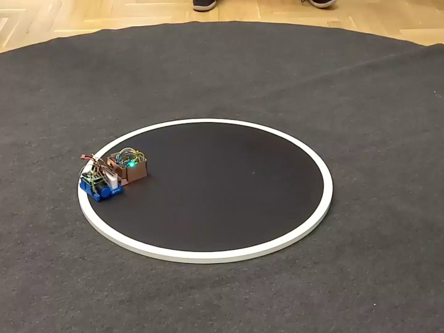
How we built a robot for minusumo competition

Many months ago two colleagues of mine and I have started collecting requirements for a rapid, fast-turning robot which meets the organizer’s regulations.
- Competition regulations
- Basic construction requirements
- Parts
- Recap of what we have
- New board, new robot
- Final result
- Lessons learned && further improvements
- Plot twist
- Things we made right
- Summary
Competition regulations⌗
- maximum 500g of weight
- maximum base dimensions are 10x10cm (however, there isn’t a height limit)
- no glueing to the ring, shooting at the opponent nor any other intentional action causing damage
- robot cannot divide into smaller parts
see this page for other common rules
Basic construction requirements⌗
Without thinking to much, we have compiled the list of (basic) requirements we have to met:
- solid, light base (preferably made from an aluminum or laminate)
- DC motors with wheels and tires
- battery
- distance sensors
- line sensors (which detect white line on the edge of the dohyō)
- control unit taking data from sensors and reacting appropriately
Parts⌗
Before building some riding construction, we had to learn how to use individual parts – scale them appropriately, take reads from them etc.
Line sensors⌗
We have used basic QRD1114 sensor with fototransistor. However, circuit containing Arduino Uno board was maybe not difficult, but crumbling with every touch.
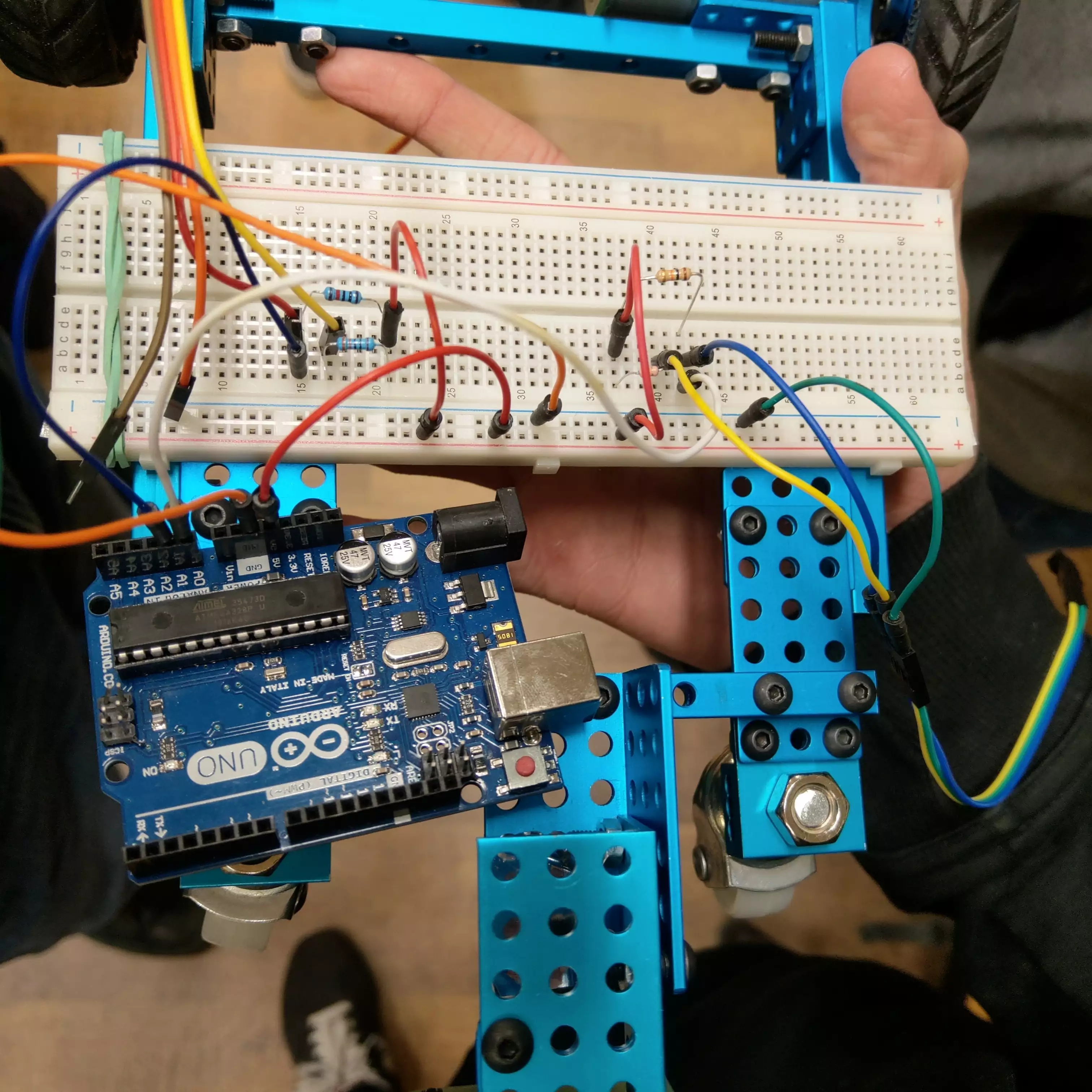
We glue two of them with tape to the prototype’s front. Somehow they held up.
As each of line sensors per a corner isn’t mounted at same height, data read from each of them must be (individually) compared to its previous read. We assumed that the robot had ran over the line when the measurement differed from the previous one two times.
Detailed steps:
- Put the robot inside the ring <=> on a black surface
- Set the reference value (an individual value per sensor)
- Class function
on_line(latest_measurement) -> boolchecks if the measurement is two (or more) times smaller than the reference value
(as the measurement of black color is near900–1000and white tends to slight above0value)
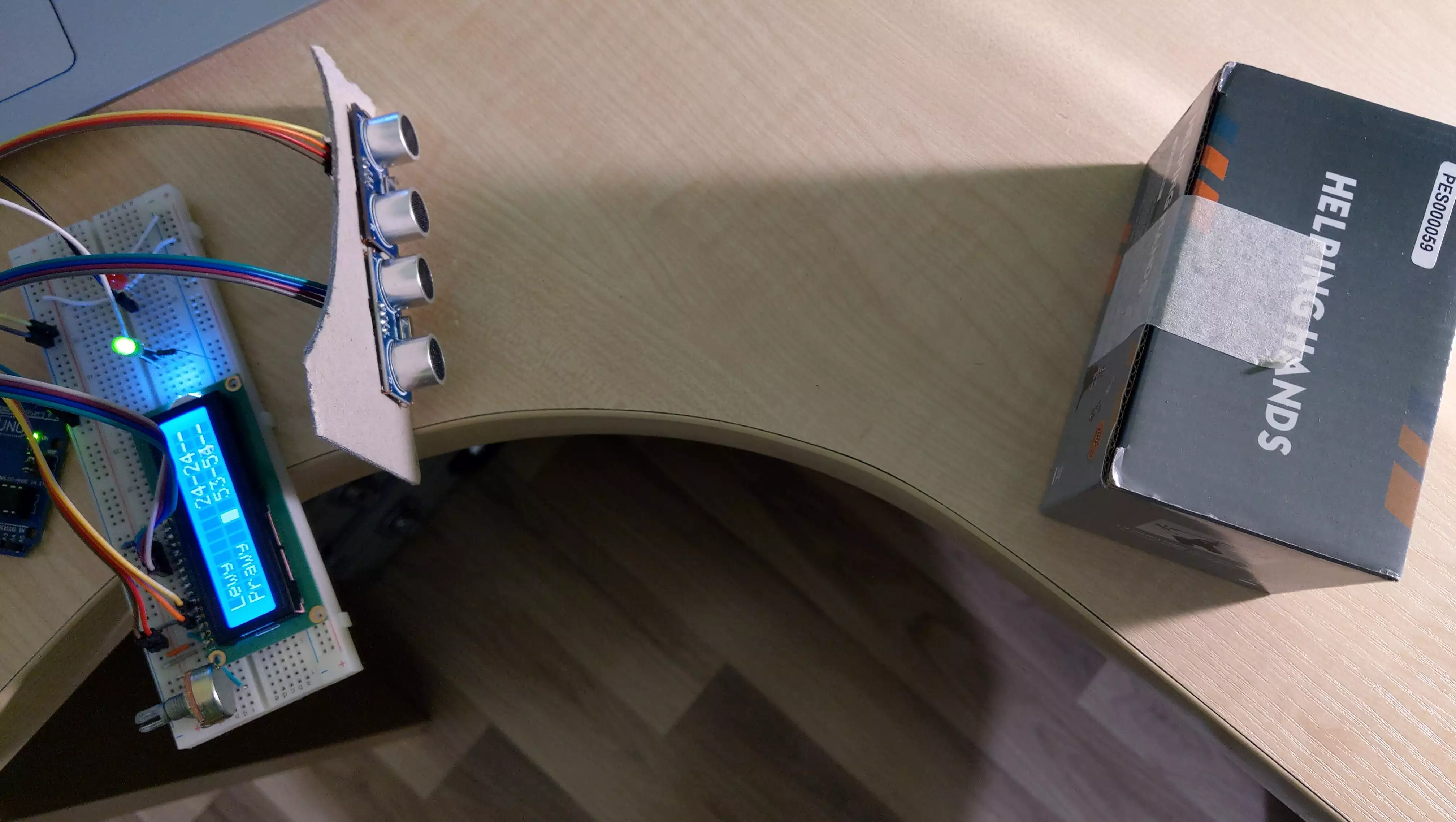
Distance sensors⌗
HC-SR04⌗
At first, we were using ultrasonic HC-SR04 sensors. However, they came with reads speed limitation – cannot provide reliabe measurements when the robot was fast turning.
ToF⌗
In order to provide fast measurements (below `40ms), I have bought Time of Flight VL53L0X sensors. These laser-based sensors are by the way ideal for small holes on the front of the competition robot.
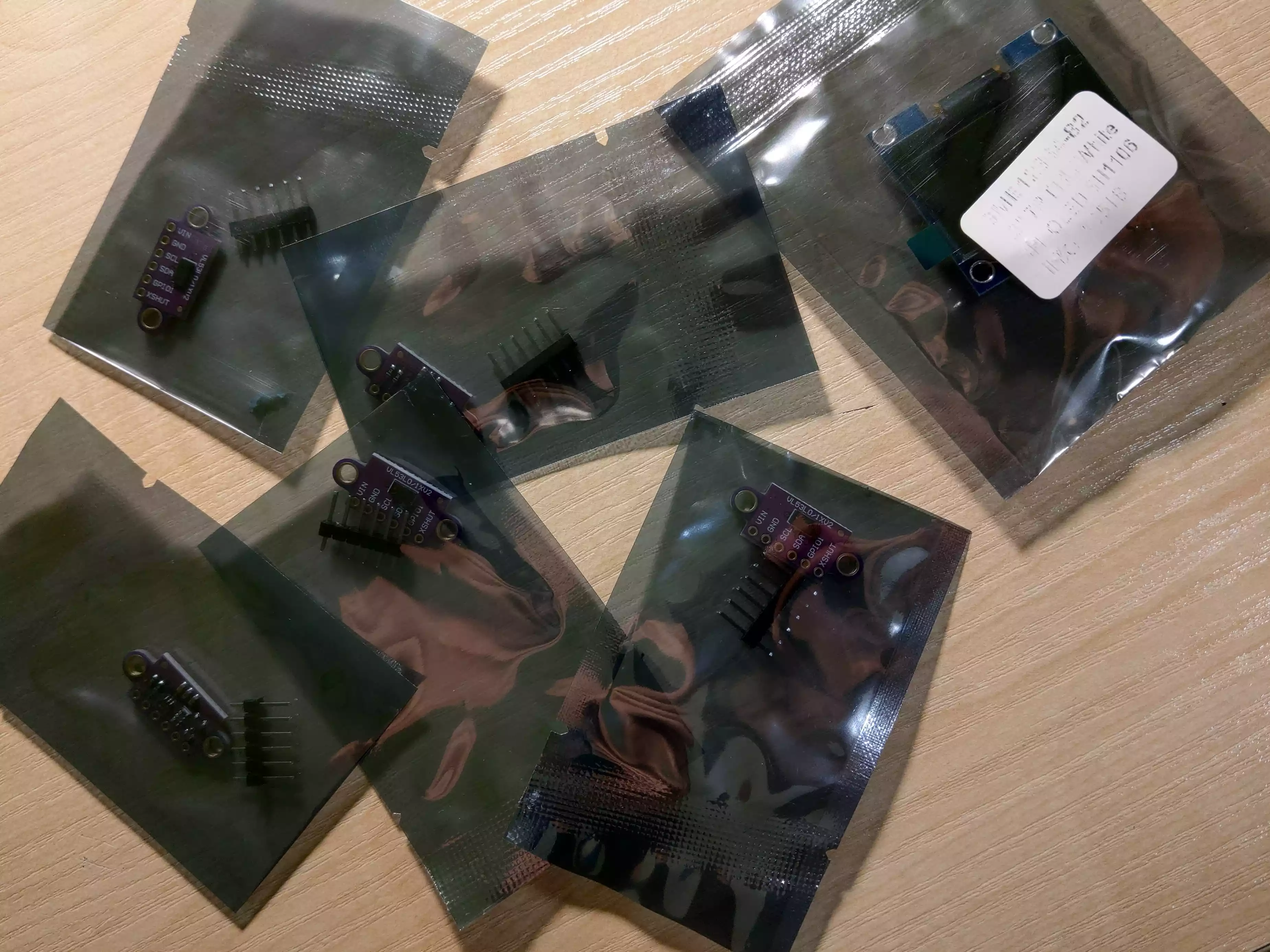
However, these sensors use I2C communication protocol and thus have to have their unique adresses set.
VL53L1X is an improved version of VL53L0X. They differ in maximum distance (VL53L1X has the farther – up to 4 meters). My ones comes from Aliexpress descripted as VL53L0X/VL53L1X. They are pretty cheap happily.
Pololu’s datasheet (at section 2.6.1) says that VL53L1X sensor has XSHUT pin which is responsible of powering up/waking up when Vcc (1.8V or 2.8V when special bit is set) only delivers the power.
Initialization steps:
- Set
XSHUTpin (of one sensor) toHIGH - Set its I2C address (other than
0x29– at most one sensor may have it) - Wait some time (about 20-50ms)
- Repeat for another one
Note about I2C addresses: the documentations says that the sensor has
0x52address by default. However, this list do not contain VL53L1X sensor at0x52address. However, my ones have0x29initially and this is known value.
We also set timeout to 500ms for I2C initialization and measurement timing budget to 40 000ns == 40ms
(function’s parameter wants value in nanoseconds; 20000ns is the minimum).
VL53L1X sensors (as well as the older ones) have both single-read and multi-read (continuous) mode. The latter provides only the latest valid measurement. In other words, the latest measurement overwrites the previous one so there is always a (latest) value to read. We set the mode to the continuous of course.
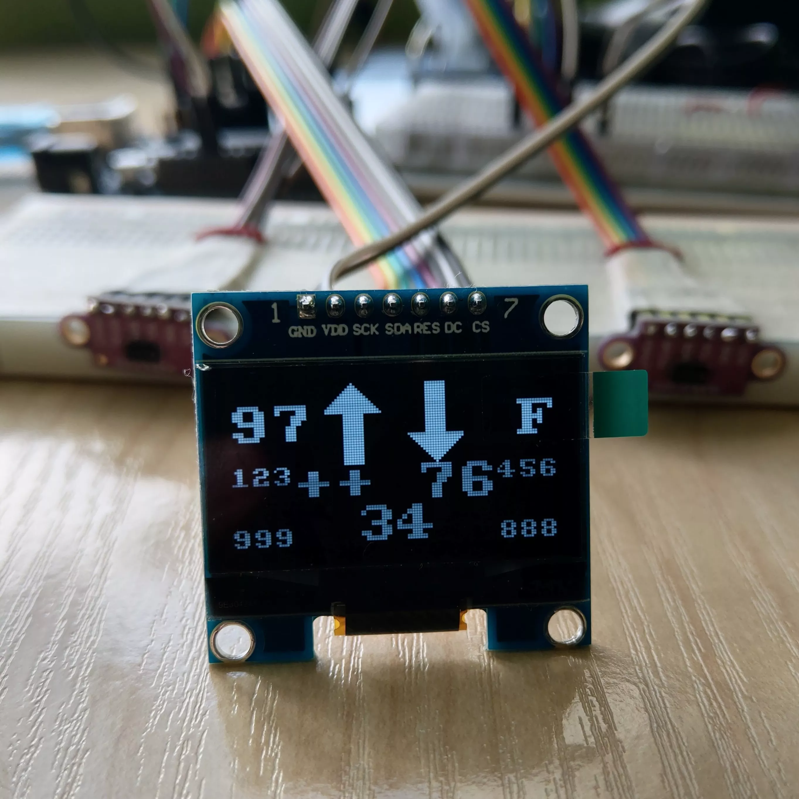
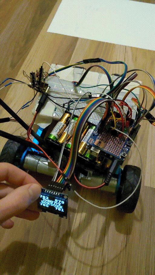
OLED display⌗
Showing measurements values at a laptop screen isn’t convenient at all, especially in next stages of testing when robot rides.
Naturally, I came up with an idea of using OLED display to present values from sensors.
I have created layout for 128x64px OLED display:
- at upper corners the display shows percentage of power for each motor (from
0to99in digits,Frepresents100as100has three digits), - at the upper middle you see directions in which each motor rotates (visible at a glance compared to signed values),
- at each corner of the bottom half show
0–1023measurements from line sensors, - and the last but not least, measurements1 from three (eventually – only front two) ToF sensors at corresponding to their location on robot’s front.
Motors⌗
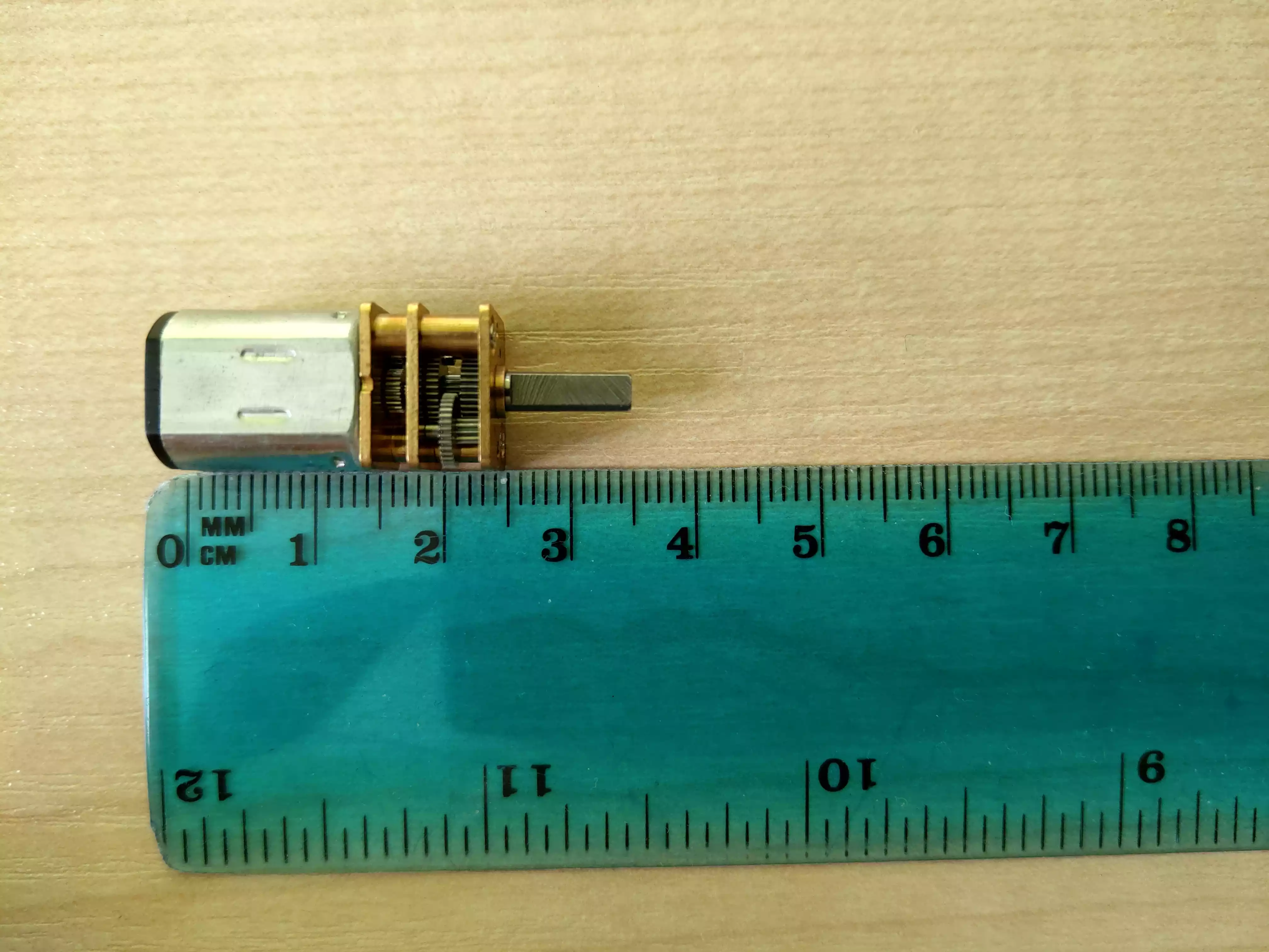
The choice of motors was dictated of course by size, price and power (both torque as well as RPM – revolutions per second). The applied voltage did not applied as majority of motors have 6-12V range, often specified in their datasheet2. Although finding a motor which fulfills power and price (two and as many as two motors are needed) requirements isn’t hard, dimensions play a huge role.
Specific numbers depend on author’s idea, however I do not find idea of shifted motors by ~2cm to each other as a good proposal, especially in terms of stability.
We have found a 25x12x10 (mm) motor + 9x3 (mm) shaft with 30kg*cm (3Nm) torque. These motors proved to be a little too weak during competition – we had struggled with a opponent’s robot with rubber tyres and high-torque motors.
Finally, we won that battle ;)
H-bridges⌗
Their name is derived from its common schematic diagram representation and these electronic circuits switch the polarity of a voltage applied to a load.
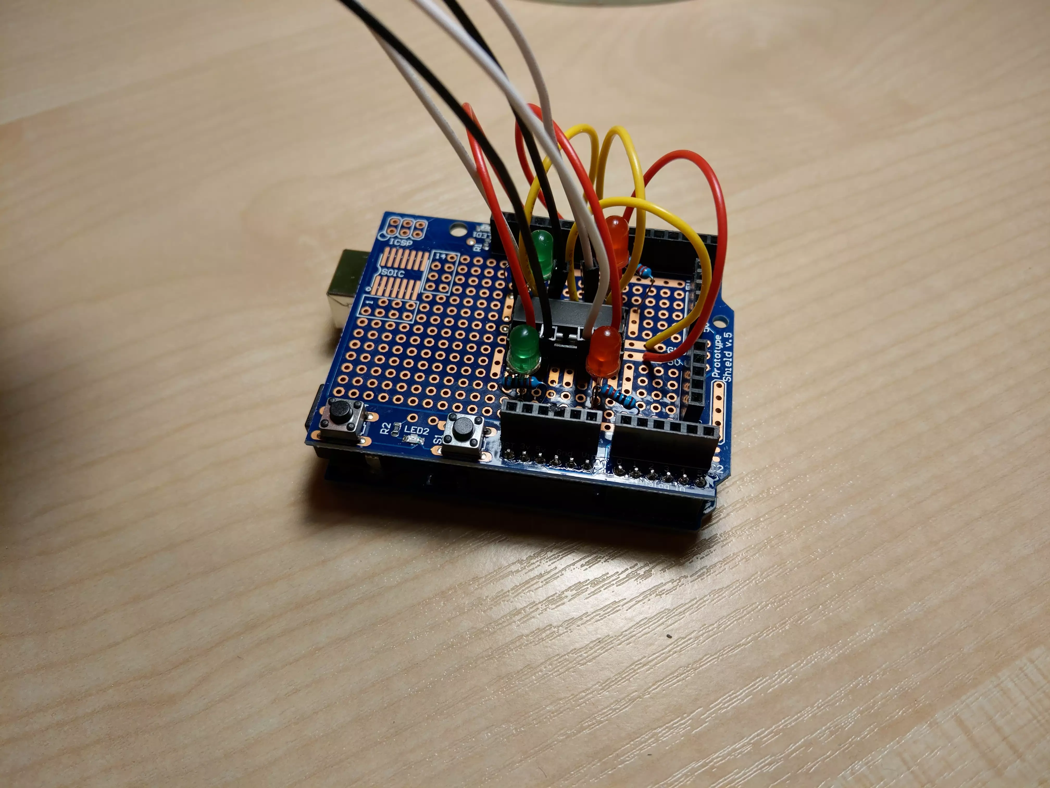
Arduino Uno Proto Shield⌗
I soldered a base for one H-bridge into Arduino Uno shield board and included some LEDs indicating direction in which robot drives. These were helpful during debugging as we could be sure that current flows and flows through the proper pin.
Recap of what we have⌗
Putting all parts (HC-SR04 sensors + OLED display + big old motors + Proto Shield with H-bridge) together, as we were improving robot construction by small steps, we had this:
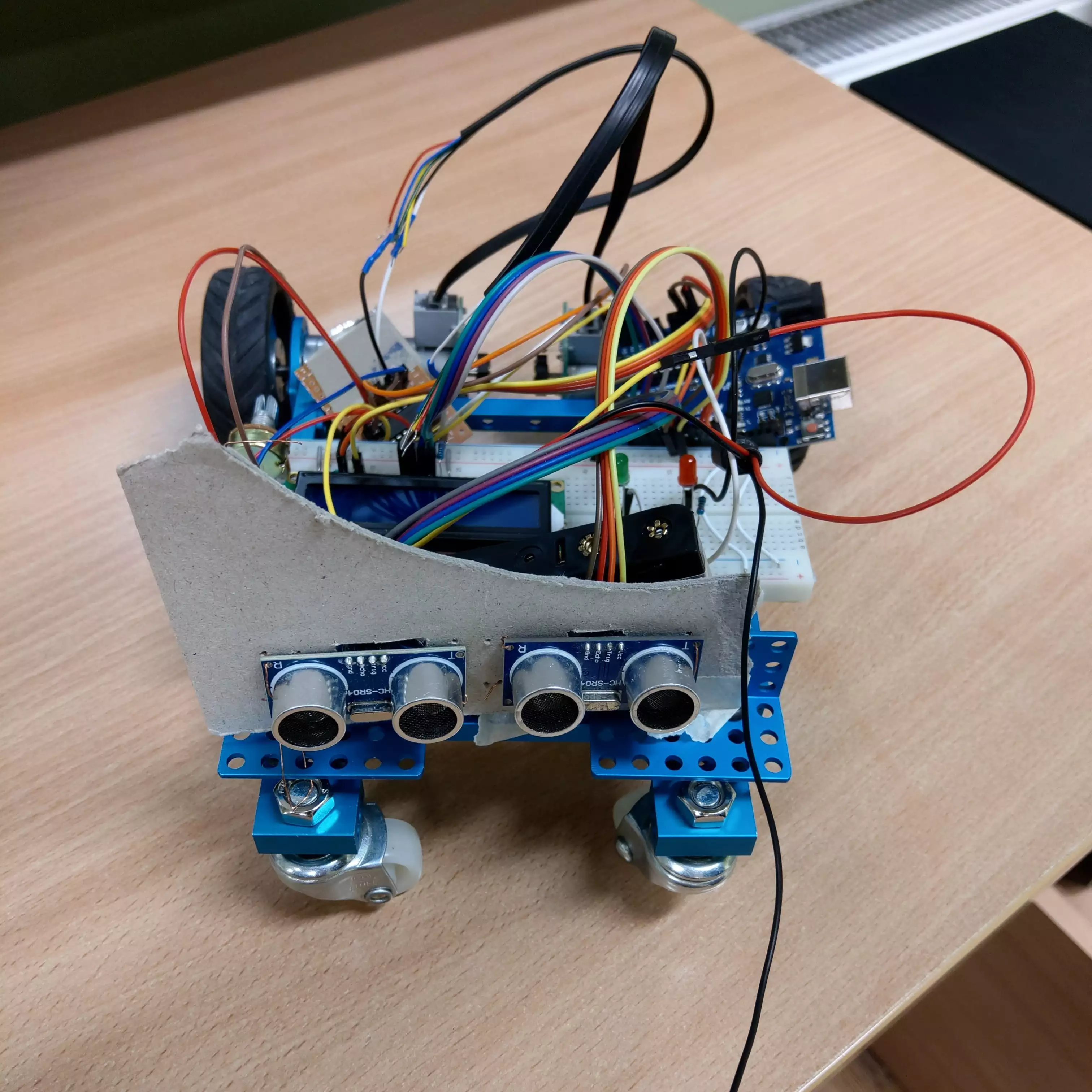
and then, after replacing HC-SR04 with ToF sensors:
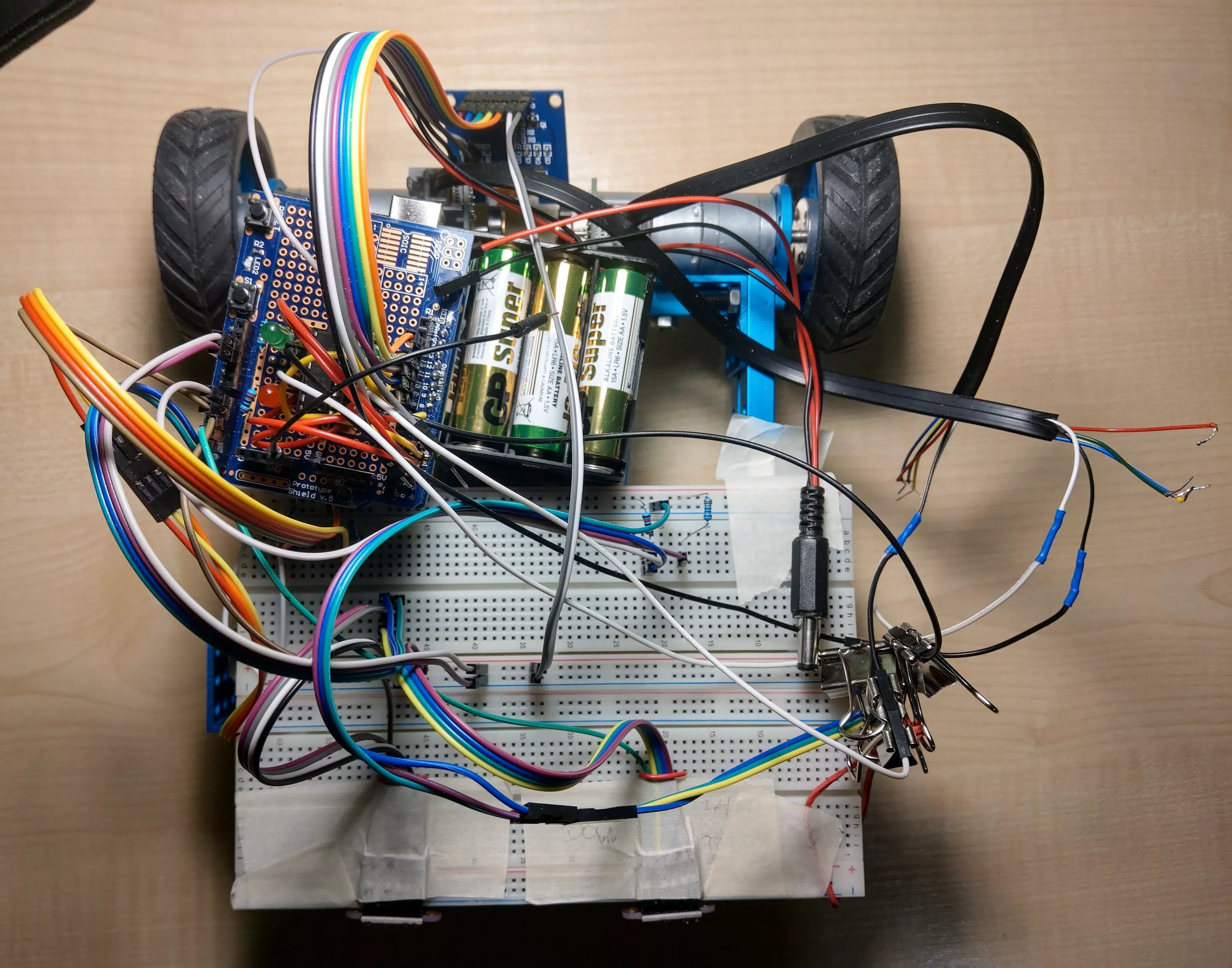
and even running:
New board, new robot⌗
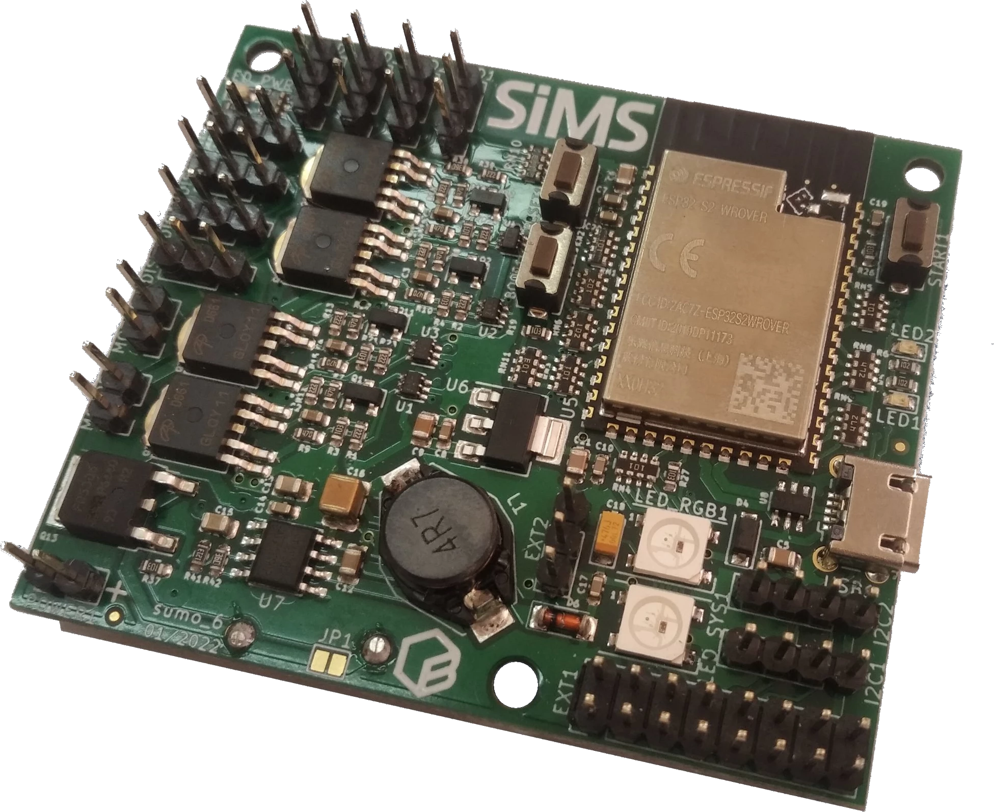
Two months before the competition started, we had received a new custom board with mounted Espressif’s ESP32-S2 processor (WROVER). That one was made by a partner (and sponsor) of organiser.
Some features and data about the new board:
- powered by voltage
6–14Vby pins or microUSB port - has built-in DC motors support3
- has RESET, BOOT, START buttons
- is equipped with two RGB LEDs – one for internal MicroPython signaling, one for a developer – and two standard LEDs
- along with two I2C ports, it has 8 additional general-purpose pins (others in the two-row set of 20 pins are
3.3V,5VandGND) - can run ESP-IDF, Arduino or CircuitPython
We had choosen the last one option.
Wheels and tyres⌗
Using standard tyres which are commonly seen in remote-controlled car were our weak point. We should rather lean towards wider rubber tyres.
However, it should be noted that very wide tyres interfere with turning but this applies mostly to much wider ones than we thought.
And also, as three and only three points in space always determine the plane, we used a small aluminum rolling ball mounted near the front of the laminate base.
Floor plate⌗
We chose laminate as material for a floor plate and side walls. Therefore, our team member have cut it into a grid’s parts and glued using two-component adhesive.
We had to file the laminate around 2–3 milimeters in order not to have any gap between robot and ground. And that was a huge mistake – filing took far too much time in relation to what we assumed.
To make matters worse, the time spent was not matched by quality – we have achieved a barely satisfactory result.
And this was evident during the fights with the robots equipped with the blade in front when the opponent’s robot was picking us up a little and moving us around as it pleased.
Batteries⌗
We used middle-sized three batteries, 3.7V nominally (4.2V when full-charged), 400mAh each, connected in series so as a result we had from 4.2V * 3 = 12,6V to around 10.8V4 power source which lasts about an hour of robot running.
Both batteries and DC motors were glued with the two-component adhesive.
Power sources were simply located at the middle of floor as its weight wasn’t a big deal.
We have also loaded the robot with lead cubes nearly 500g of mass.
Code rewrite⌗
Former board was using Arduino library on top of the C++. However, as we have choosen CircuitPython/MicroPython as a platform to use, we had to rewrite our code. What’s more important – must search a different library for ToF sensors.
All written code (maybe except few modifications hardly before the competition date) is under Gitlab control here.
ToF library⌗
We have used Adafruit library, in which – no long before the board arrived – fortunately someone had implemented data polling feature. This change was crucial to provide non-blocking running for our program. Thanks whogben!
If on line⌗
As each line sensor shows not so small difference in value to others, we used a reference value so that each sensor decides if it detects white line based on its own data set at the start time.
Starting⌗
Regulations dictate that the robot starts 5 seconds after pressing the button so we check if the time period passed:
now_timestamp = time.monotonic_ns()

while time.monotonic_ns() - now_timestamp < 5_000_000_000:
    time.sleep(0.01)
Stopping⌗
Most often we picked up the robot after the round was over.
However, for testing purposes, we were using stop() method like stop when it detects white line. In order not to destroy PWM pins, the code was checking whether the last change took place no more than 5 nanoseconds ago.
Debugging⌗
We had been using an OLED screen for debugging the Arduino Uno board before Espressif’s board have landed.
However, RGB LED provides wide variety of signals to show and it was crucial during checking if a code crash (and stopping of motors) was caused by wire disconnection, improperly initialized ToF sensor or a bug in code.
When working with hardware, as always, we saw a lot of strange errors, including our own slip-ups.
We made debugging process a lot easier by sending logs through WiFi to the colleague’ phone. At the same time the same log was printing at the console (CircuitPython has Python interactive prompt including stdout).
We had wrapped all function calls in another function and the latter one was inside try-except block. The except block included code changing the diode color to red and printing exception’s backtrace5 to a WiFi socket.
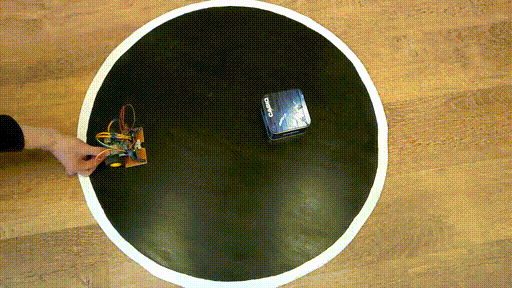
Final result⌗
The robot rides:
- at 90% speed when both sensors see the opponent (<=> its measurements are below 77cm, which is the diameter of the ring)
- at 50% speed by motor on which side the opponent isn’t being seen (and the other motor is stopped)
- at 12% (positive on one, negative on the other) when searching for an opponent – changes the direction after a few seconds
However, despite the last point, our robot rides at 40% (updated to 60%) of power when the time since the last sight of an opponent is no more than a second.
Lessons learned && further improvements⌗
Different strategies⌗
We faced different opponents, some with high-grip wheels and powerful motors but with an exposed bottom – prone to undercutting, others with a sharp and very low-set blade at the front. Therefore, we should have at least two modes of combat – one as before, the other encircling and hitting from the side.
How?
I hope you remember board description and different buttons for start.
However, it seems to me that there is a need to use a gyroscope (anglemeter) to encircle.
Sadly, we haven’t had the time or many tests with a real, worthy opponent.
Precise-made casing⌗
Next time, I would try at all costs to use a 3D printer to print a solid, one-piece casing that moves over the ground by fractions of a millimetre. This would definitely prevent undercutting by at least one of the opponents.
Grinding bottom casing of the laminate by hand was a crying shame.
Smaller board⌗
From the perspective after the competition, we needn’t have used new ESP32-S2 board as it was too large and didn’t provide more features than Arduino Nano.
Choosing Nano board would save a lot of space, in particular allowing the board to fit between the motors and the front blade.
Therefore, access to the batteries would be much easier and the robot itself would be lower.
Also, we should divide batteries between board and motors in order to ensure uninterrupted operation of the CPU and sensors.
Plot twist⌗
The above advice is unquestionably relevant.
Nonetheless, one team’s robot did not have these design faults but still lost the fight in the finals!\
Why? It was undercut from the side and pushed out of the ring.
Nothing is certain!
Things we made right⌗
Time of Flight sensors usage⌗
As you may have noticed, when it comes to ToF sensors I am in my element.
From the perspective of the robot’s combat performance, which:
- had precisely-made casing with really sharp aluminum edge at the front
- was 5cm height (due to choice of Arduino Nano board and small battery)
- whereas had three Sharp GP2Y0A41SK0F IR sensors instead of some fast ones
there is no doubt that you have to use rapid-outputting sensor or you would be undercut (yes, even this robot lost the fight in finals).
Decision priority based on sensor measurements⌗
Although the basic goal is not to be out of ring, be sure that your robot can push your opponent out of the ring even if you were on the ring line for a few seconds. Therefore, it is crucial to check priority of if statements and its decisions in the code.
Summary⌗
When it comes to build a sumo robot in any weight category, in addition to the large amount of spent time, well chosen components, algorithm for any situation, it is definitely worth testing the robot during real battles.
Cheers!
-
Numbers represent distance in centimeters except
++as out of range (as any measurement which is over 100cm is not valid because at any time the opponent is not more than 77cm away from us). Two exclamation marks!!represent an error during value reading (in most cases – due to poor wire connection) ↩︎ -
Consequtively, these values are: voltage, (speed, torque, current) x (no load, maximum efficiency, stall) ↩︎
-
Instead of using H-bridges, we directly open/close transistors. That’s why in code you can see some
5msdelay between operations to avoid damage. ↩︎ -
Although a cut-off voltage for each battery was
2.75V, we perefered to replace and charge them. ↩︎ -
We struggled a bit with logging the backtrace. Functions which were related to traceback only printed code number (see
errno -lfor them). Finally, I have used my Python knowledge and have foundtraceback.format_exception(value=ex, etype=type(BaseException), tb=ex.__traceback__)as working ↩︎